I haven't posted much. Been busy with binging Netflix and my wife and I getting back into World of Warcraft.
It is a lot of fun to quest together.
But the holidays are coming up and I have some time off, my goal is to get the Globetrotters table up and running by New Years.. wish me luck!
Wednesday, December 13, 2017
Saturday, October 14, 2017
installation
Now that the Hot Tip is working again, I have started work on re-assembling the Harlem Globetrotters pinball table back box.
After getting it all painted up, the next step was to get the shell pieces back installed.
Its amazing, how I am able to miss important pieces when photographing the old set up. I took over 40 pictures of the old shell as I took out the boards, mounting brackets and metal sheets, and I never got one picture that showed if two pieces were supposed to connect or not.
oh well, I am doing my best on this and should soon be able to turn it back on and see if it works!!!
Tuesday, October 10, 2017
Hot Tip Finally Working
After my soldering woes, I was getting close to throwing in the towel on the Hot Tip and start looking for a replacement board.
I pulled the board again, scraped some more, plugged the board back in, turned it on. And again - no solenoid action except one that was on continuously until the fuse blew.
I lifted the playfield and thought I might unsolder the solenoid that was having trouble to see if that helped, but when I looked underneath it looked to be in great shape and worked manually just fine. Besides, the only thing that changed was my soldering in the new DIP-Switch.
sigh...
Time to pull the board out and scrape some more, I must still have a short where I accidentally over-soldered the connections.
This time I noticed one of the chips was halfway out of the chip holder, one side was up high and the other down low. I pushed it in, scrapped some more and put it all back together.
Low and behold it worked!
Now that I think about it, it may have been the chip all along and I may not have needed to do the scraping at all.
But, now everything seems to work. In test mode, all of the lights, bumpers, switches, etc. all fire just fine. The game plays, scores count, everything is good except...
Now the flippers won't work.
...sigh...
I checked the fuses again, and traced the wires I could see, but whey would any of that have been messed with. All I did was unplug the circuit board a bunch of times. I was really getting nervous that I had somehow totally broke the table and was getting ready to post a "help me" message to the pinball forum when I had a thought tug at me. I seem to recall something similar happening on the table. I could not pin it down and I spent all evening trying to remember. Then just as I was heading to bed, I remembered!
There was an extra wire on the connection between the head and the body. Although I never touched it, it was worth checking.
Low and behold (again) it was disconnected!
I reconnected the wire and the flippers started working. It appears the table is back to functioning again. But it was past bedtime so I didn't have much time to try out the DIP-switch and see if it worked correctly.
Today I dug back through my posts and found the relevant one. It details exactly the same problem I had. I don't know why the wire was disconnected, it doesn't plug into the boards I was removing, I must have just hooked it somehow during one of the processes. But hey, at least it is up and running!
Sunday, October 8, 2017
Another New Table - Meet the Williams Argosy ElectroMechanical Pinball
After playing with the United Brazil Bingo Pin ( link ) I decided that I wanted to try an EM pin.
EM = ElectroMechanical,meaning the pinball machine was made before electronics became available and so it was all done with pure mechanics. Wheels and gears to keep track of targets, scores, balls, money, etc.
Its an interesting mechanical problem and toying with one seemed like it would be a lot of fun. So I kept a lookout for one. This last weekend one popped up. It was an estate sale and there wasn't a lot of info but it was definitely a EM pin so we thought we would go down and take a look.
It turned out to be an Williams Argosy and it was in great looking shape! the backglass was perfect
and the playfield showed almost no signs of wear. It turned on, lights came on, made noise, the wheels clanked but it would not play.
Since it didn't work. We negotiated a price and I think both parties came out happy.
They got some money and I got a pin that looks to be in good shape, hopefully it is something easily fixable!
EM = ElectroMechanical,meaning the pinball machine was made before electronics became available and so it was all done with pure mechanics. Wheels and gears to keep track of targets, scores, balls, money, etc.
Its an interesting mechanical problem and toying with one seemed like it would be a lot of fun. So I kept a lookout for one. This last weekend one popped up. It was an estate sale and there wasn't a lot of info but it was definitely a EM pin so we thought we would go down and take a look.
It turned out to be an Williams Argosy and it was in great looking shape! the backglass was perfect
 | |
| Argosy Pinball Backglass |
Since it didn't work. We negotiated a price and I think both parties came out happy.
They got some money and I got a pin that looks to be in good shape, hopefully it is something easily fixable!
Harlem Globetrotters Soldering
Now that the box for the Harlem Globetrotters pinball table is painted and looks good, I am starting to put everything back together.
As you may recall I pulled everything out of the header ( link ) and painted it.
Time to put it all back in. As I re-assembled the light-panel (The wood with the lights on it) I noticed one of the LED displays had what appears to be burned out resistors on its little board:
Another soldering disaster!
While I was able to get the resistors out of the board, I managed to deconnect the tiny traces and ring that the solder is supposed to connect to - why is my soldering so bad???
I spent all evening soldering them back in, using a meter to verify I have connectivity but I have no way to test them until I get it all put back together.
Looking at my soldering iron, I am going to try and lower the temperature on it. I have it set all the way up, under the theory that hotter means faster but it could be its just too hot and is screwing things up. We will see if that helps.
In the meantime the Harlem Globetrotter table awaits reassembly as somehow I managed to lose one of the back pieces of sheet metal. Not a big deal but it means a wait until I can go back to the store for more.
As you may recall I pulled everything out of the header ( link ) and painted it.
Time to put it all back in. As I re-assembled the light-panel (The wood with the lights on it) I noticed one of the LED displays had what appears to be burned out resistors on its little board:
 | |
| Burned out resistors |
While I was able to get the resistors out of the board, I managed to deconnect the tiny traces and ring that the solder is supposed to connect to - why is my soldering so bad???
I spent all evening soldering them back in, using a meter to verify I have connectivity but I have no way to test them until I get it all put back together.
Looking at my soldering iron, I am going to try and lower the temperature on it. I have it set all the way up, under the theory that hotter means faster but it could be its just too hot and is screwing things up. We will see if that helps.
In the meantime the Harlem Globetrotter table awaits reassembly as somehow I managed to lose one of the back pieces of sheet metal. Not a big deal but it means a wait until I can go back to the store for more.
Hot Tip Wounds
When my son arrived for vacation, the only pin I had in working condition was the Hot Tip, and it had a problem. The DIP-Switches on the motherboard had broken and I was trying to manually set things by sliding the tiny sliders with a pair of needle nosed pliers.
Once he was gone I decided it was time to replace the switches. It seemed easy enough, unsolder the old switch, solder on the new switch.
The old one came off easily enough, and I soldered the new one on:
However when I turned the system on, it groaned (hummed) and made weird sounds and woudl not work.
....sigh....
so I reflowed the solder intro each socket. No change...
so I reflowed and added more solder. this time (or perhaps the first time) I noticed that it looked like I had melted the green stuff and there might be a connection under it:

Arrgghh.. another self-inflicted wound!
I ended up scraping it away with a knife. But I have been unable to test it as all the fuses are blown.
I replaced them but the one that runs the solenoids keeps blowing, but I noticed one of the solenoids was stuck in the on position and it finally went back, but that was my last fuse... so back to the store to buy another batch of fuses and see if that was the problem or not....
Once he was gone I decided it was time to replace the switches. It seemed easy enough, unsolder the old switch, solder on the new switch.
The old one came off easily enough, and I soldered the new one on:
 | |
| The new dip-switch |
However when I turned the system on, it groaned (hummed) and made weird sounds and woudl not work.
....sigh....
so I reflowed the solder intro each socket. No change...
so I reflowed and added more solder. this time (or perhaps the first time) I noticed that it looked like I had melted the green stuff and there might be a connection under it:

Arrgghh.. another self-inflicted wound!
I ended up scraping it away with a knife. But I have been unable to test it as all the fuses are blown.
I replaced them but the one that runs the solenoids keeps blowing, but I noticed one of the solenoids was stuck in the on position and it finally went back, but that was my last fuse... so back to the store to buy another batch of fuses and see if that was the problem or not....
Monday, August 28, 2017
Learning spray-painting the hard way
After my first attempt at spray painting, I opted for a much larger gun. Specifically the 47016 gun. According to the web page it:

- Sprays enamels, lacquers, metallic, and urethanes
- High versatility for automotive and hobby projects
- Ideal for spraying base coats and primers
Sure sounded ideal. So I picked it up along with my can of Killz Primer.
The Killz website says I can spray at 2,500 psi to 3,000 psi which is far more than my air compressor can deliver.
The spray gun said it was supposed to run at 50 psi, so I set the compressor output at 50 and gave it a try. At first it seemed to work, then soon I got blobs of paint on the tip and the end result of all of this was total crap. The carefully smoothed surface became a mess of blobs and mottled paint:

I obviously need a LOT more experience in painting, but I don't have time to experiment on the cabinet. I want to get it working!
Out came the rattle-can
Wednesday, August 16, 2017
preparing the Harlem Globetrotters Pinball cabinet
After finishing up the Steampunk-Inspired lamp, I have turned my attention back to the Pinball tables. Specifically, getting the Harlem Globetrotters table topper fixed up.
While the topper wasn't in terrible shape, there were bad edges, dents, the paint was faded and the box was covered in lead-based paint. So it definitely needed some work.
Plus this was a chance to learn a couple of things:

After gagging from the smell! I learned two key pieces of information:
But at last I had it good enough for a first coat of primer.
I pulled out my handy-dandy portable spray booth, set it up in the garage, loaded the top in it:

Got out the 3/4 Oz. Quick-Change Airbrush Kit I purchased:
 and started in!
I quickly discovered that the 3/4 Oz. airbrush was far far too small for this use. It is probable that I cannot get it adjusted to its maxiumum abilities but it is not even close. At its best, all I could produce was a light paint spray about 1 inch wide.
The good news was I was able to learn a bit about using a spray gun, the bad news was I need to purchase one 2 or 3 times this size.
While the topper wasn't in terrible shape, there were bad edges, dents, the paint was faded and the box was covered in lead-based paint. So it definitely needed some work.
Plus this was a chance to learn a couple of things:
- how to do wood repair - specifically how to use Bondo (which is the recommended filler from a lot of repair gurus)
- How to spray paint. I have never used a spray gun - I have always used rattle cans (or a roller) for painting.

After gagging from the smell! I learned two key pieces of information:
- Bondo sets up quickly! I was only halfway through my pile of goop when it started hardening and would not spread easily on the wood.
- A thin coat is all you need! I laid it on thick, thinking it was like the stuff you put on sheetrock - easily sanded off - hah! I had to sand for hours to get rid of the big ridges and blobs I left all over the wood...sigh
But at last I had it good enough for a first coat of primer.
I pulled out my handy-dandy portable spray booth, set it up in the garage, loaded the top in it:

Got out the 3/4 Oz. Quick-Change Airbrush Kit I purchased:

I quickly discovered that the 3/4 Oz. airbrush was far far too small for this use. It is probable that I cannot get it adjusted to its maxiumum abilities but it is not even close. At its best, all I could produce was a light paint spray about 1 inch wide.
The good news was I was able to learn a bit about using a spray gun, the bad news was I need to purchase one 2 or 3 times this size.
Monday, July 31, 2017
Steampunk-inspired lamp - Finished!
With the shade holders put into place, the steampunk-inspired lamp was finished!
A couple of pictures of it in all its glory:


if you are interested in following the story of this lamp, check out the full thread here.
A couple of pictures of it in all its glory:


if you are interested in following the story of this lamp, check out the full thread here.
Steampunk Inspired Lamp - shade holders
Since finishing the topper on the steampunk-inspired lamp. I am down to a single issue: holding the lampshades on.
It originally looked like this:
I originally thought about just pulling in the cord but I was worried about longterm "floppyness" so I tried using epoxy to glue the shade to the end of the pipe.
That worked but when I accidentally bumped it, it broke loose.
I do not have a welder and I think the bulb-socket housing is plastic anyway. So I wanted to create something in keeping with the steampunk spirit.
My solution was to spend $1 and get a piece of sheet tin. I then cut it
into short strips. Then popping them into the vice, I bent them into rough "S" shapes:
Using some screw-on pipe squeezers (there is probably a accurate technical term but I don't know it) I connected 3 of my strips to the pipe:
Another 2 on the larger end where the lampshade actually is, then some "hammered metal" paint and misted with black to get it down to the proper look and it is locked on and solid!

The lamp is complete!
It originally looked like this:
 |
| Lampshade holder issues |
I originally thought about just pulling in the cord but I was worried about longterm "floppyness" so I tried using epoxy to glue the shade to the end of the pipe.
That worked but when I accidentally bumped it, it broke loose.
I do not have a welder and I think the bulb-socket housing is plastic anyway. So I wanted to create something in keeping with the steampunk spirit.
My solution was to spend $1 and get a piece of sheet tin. I then cut it
 | ||
| Cutting the tin |
into short strips. Then popping them into the vice, I bent them into rough "S" shapes:
 |
| Bent tin holder |
Using some screw-on pipe squeezers (there is probably a accurate technical term but I don't know it) I connected 3 of my strips to the pipe:
 |
| locking down the pipe strips |
Another 2 on the larger end where the lampshade actually is, then some "hammered metal" paint and misted with black to get it down to the proper look and it is locked on and solid!

The lamp is complete!
Friday, June 30, 2017
Steampunk-inspired lamp - topper
Despite problems with the switch, the steampunk-inspired lamp construction is going well.
The rest of the parts have come in and I am able to see if my idea bears fruit. If you recall, the original idea included a pipe-cross at the top and some kind of support for the lamp-shades themselves although the details were a bit sketchy.
With the pipes in, I was able to put the pieces together and test-fit the topper
Once it was apparent it was going to fit as indicated. The problem of running the wires through the pipes raised its ugly head. It took some real work to get the electrical wires threaded through the pipes:
Then it was a matter of holding the pipes together with one hand, fitting them into place with the other hand, holding the screw with the other hand, screwing in the screws with the other hand, guiding the wire through the hole in the support wood with the other hand..lol, thats a lot o fhands but eventually I got it done.
Now its just a matter of getting the lamp shades on the the pipes, getting the switch to work and wiring it all up!
The rest of the parts have come in and I am able to see if my idea bears fruit. If you recall, the original idea included a pipe-cross at the top and some kind of support for the lamp-shades themselves although the details were a bit sketchy.
With the pipes in, I was able to put the pieces together and test-fit the topper
 | |
| Test fitting the upper mechanism |
Once it was apparent it was going to fit as indicated. The problem of running the wires through the pipes raised its ugly head. It took some real work to get the electrical wires threaded through the pipes:
 | |
| threading the wires |
Then it was a matter of holding the pipes together with one hand, fitting them into place with the other hand, holding the screw with the other hand, screwing in the screws with the other hand, guiding the wire through the hole in the support wood with the other hand..lol, thats a lot o fhands but eventually I got it done.
 | |
| Topper is in place |
Now its just a matter of getting the lamp shades on the the pipes, getting the switch to work and wiring it all up!
Tuesday, June 27, 2017
Steampunk-inspired lamp, switch problems
One of the fun pieces of designing the steampunk-inspired lamp was the light switch. There are some cool light switches out there (link, link) but they tend to be wall switches and not lamp switches. While researching, I came across the idea of using a water valve as the light switch. Something that fits nicely with the "pipe" theme I have going on and is unexpected for a light switch.
With that in mind, I purchased a set of short pipes, switch and a valve.
The first step is to take the valve apart. The instructions warn, "It will likely be extremely tight, so you probably won't be able to simply hold the valve body in one hand and turn the wrench with the other."


 The source page was no help, just vaguely referring to some glue and epoxy to hold it together.


With that in mind, I purchased a set of short pipes, switch and a valve.
The first step is to take the valve apart. The instructions warn, "It will likely be extremely tight, so you probably won't be able to simply hold the valve body in one hand and turn the wrench with the other."

I confidently put the valve in my vise, pulled out a pair of pliers and tried to turn it. All I got for my trouble was a mess.
I got out the vice-grips, tightened them down and tried them. They literally tore the valve body metal edges off, but it would not budge.
I was worried that I had purchased a valve with the stem welded together or something. I eventually tightened down the vice-grips to the point where they dug into the metal and used my sledge hammer to hammer on the vice-grips and finally it gave way.
I ended up with a useless piece of metal:

When the next valve arrived in the mail, I started with the vice-grips and sledge technique and got it off with minimal distortion.
Next came the switch, while it would fit inside it wouldn't stay centered.

I eventually poured quick-set epoxy into the base of the unit while I held the switch in place on top. It worked and the switch was centered below the opening and able to spin.
Next up was drilling out the hole so that instead of moving the valve up and down, it spins easily.

Fortunately this was pretty straightforward and went smoothly.
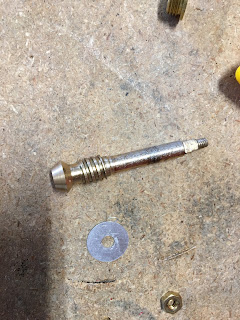
Then came the all-important "putting it all together"
Sadly, the shaft stuck down so far the threads would not engage. Looking at the shaft, I had hoped to glue the head to the switch, but I had to either grind away the threads on it or shorten the length. I opted to cut off the end:


That gave me the right amount of clearance. The valve-stem holder had enough clearance to screw on, the valve-stem spun freely and and sat nicely on top of the switch.
All I had to do was glue the valve-step to the top of the switch so when I turned it, it would also turn the switch.
I dropped some epoxy on the switch, closed it all up tight, waited my 5 minutes and.....
The valve handle spun freely. Opening it up, the epoxy didn't stick to the switch plastic.
I scuffed up the top of the switch to give the epoxy something to bite onto and tried again.
same problem, the epoxy pops off the plastic switch housing...seriously, who makes switches out of epoxy-proof plastic!
I'm going to try some super-glue and see if that will work... I am so close!!
Bingo Pinball not resetting
After some discussion online with the experts on what my next steps should be, I plugged the United Brazil Bingo Pinball machine and and manually set it up a couple of games (by pushing on the lever).

When turned on, it is supposed to rest back to zero. I plugged it in and turned it on:
and it runs! but it never resets back to zero.
After digging around and looking at it, it looked like the solenoid that was pushing the reset level wasn't doing its job....seemed like a straightforward sticky solenoid plunger.
I pulled the unit out of the Bingo:

and pulled off the solenoid.
Surprise! it was in great shape, not mushroomed or sticky at all. In an effort to figure out what is going on, I managed to film myself working the unit manually:
Analyzing the movement, it looks like the little lever connected to the tiny spring is not moving the way it should around that shaft. I'm going to pull off the lever and clean the shaft.
Monday, June 19, 2017
A big thanks
A big shoutout to the previous owner of my United Brazil bingo pinball game.
In order to get the Brazil upstairs and into my workarea, I had to remove the topper. No big deal, those come off all the time. But in the ancient pre-electronics era when this thing was made (circa 1956) they didn't have modern connectors.
So what did they do?

They used an ancient knife-connector style of thing. The problem is that the "knives" fit in multiple connectors.
I searched desperately for some method other than the "try it and see if smoke comes out" method. Fortunately the previous owner was smart enough to put a dot of colored paint on each connector - you can see the yellow dot easily on the top of the leftmost connector.
Then it was simply a matter of checking each "knife" and matching up the colors!

As a side benefit of this work. The lights now have come on, so apparently part of my problem was just corrosion on the connectors!
Thursday, June 15, 2017
Cleaning the Pinball Wiring
With all the postings about my Steampunk-inspired lamp, it is hard not to forget that I am still working on the renovation of my Harlem Globetrotters World Tour pinball.
One of the key pieces is getting the wiring cleaned. It sounds simple to clean a wire but in reality you've got a large bundle of wires in poor, oily, dirty condition and it can be a lot of work to clean them.
After reading of several different techniques, I opted for Vid1900's guide. He basically says to throw it in the dishwasher, it will be fine!
So it was with considerable trepidation that I put my precious wiring into the dishwasher, worried about the colors on the wires (what if they all come out white!) worried about the connectors (what if the old plastic softens and the connectors fall out) worried about the moisture (what if water gets under the insulation and rusts the wires)
Per the recommendation, I put it on "High Temp Pots and Pans" rather than "gentle," crossed my fingers and pushed "Start"
90 minutes later I had a perfectly clean wiring harness!
it looks like everything worked perfectly. My blue tape with labels on it even survived.
I fired up the air compressor and blew out the moisture still trapped in the connectors just in case. But it all looks good!
whew
One of the key pieces is getting the wiring cleaned. It sounds simple to clean a wire but in reality you've got a large bundle of wires in poor, oily, dirty condition and it can be a lot of work to clean them.
After reading of several different techniques, I opted for Vid1900's guide. He basically says to throw it in the dishwasher, it will be fine!
 |
| Wiring harness in the dishwasher |
Per the recommendation, I put it on "High Temp Pots and Pans" rather than "gentle," crossed my fingers and pushed "Start"
90 minutes later I had a perfectly clean wiring harness!
 | |
| Cleaned wiring |
it looks like everything worked perfectly. My blue tape with labels on it even survived.
I fired up the air compressor and blew out the moisture still trapped in the connectors just in case. But it all looks good!
whew
Tuesday, June 6, 2017
Brazil backglass artwork continues
Work continues on the Brazil backglass artwork.
I have made it to a pretty hammered section so the progress is slow. Part of the interesting work is attempting to duplicate the artists casual style.
For example, this is a section of a scan of my original glass:

What you are seeing is a bit of the pennant on the top of a sailboat mast and the shoreline in the background. Note how the white of the flag at the top does not match the black outline. The "shore" is even worse, with the black lines mostly working as a guideline.
It means that I don't have to be too perfect as the original was not photo-perfect, but I want it to be as faithful to the original as possible.
Below is a side-by-side section of the sailboat. On the right is the original, not much there... on the left (top) is my best guess of what the sailboat looked like originally:


Note how the lines are not perfect. I hope I did a faithful job on it. Below is a GIF showing both compared:

One sailboat down, 2 more to go.....Work continues!
I have made it to a pretty hammered section so the progress is slow. Part of the interesting work is attempting to duplicate the artists casual style.
For example, this is a section of a scan of my original glass:
What you are seeing is a bit of the pennant on the top of a sailboat mast and the shoreline in the background. Note how the white of the flag at the top does not match the black outline. The "shore" is even worse, with the black lines mostly working as a guideline.
It means that I don't have to be too perfect as the original was not photo-perfect, but I want it to be as faithful to the original as possible.
Below is a side-by-side section of the sailboat. On the right is the original, not much there... on the left (top) is my best guess of what the sailboat looked like originally:


Note how the lines are not perfect. I hope I did a faithful job on it. Below is a GIF showing both compared:

One sailboat down, 2 more to go.....Work continues!
Wednesday, May 31, 2017
Steampunk Inspired Lamp -Legs Are On
Last posting, I documented the lamp legs.
Now that the various parts have come in and the wood has been stained and clear-coated, it is time to put it all together!
The first step was to create a small triangular brace inside the box. Since the wood is just nailed together on the edges without any central support, I was worried it might collapse if pressure was applied.
So I cut out some triangles, sized them down so they wouldn't full the inside and glued them to the box-halves.

That gave me some good bracing, but when I put the box-halves together, although the braces fit together:

it didn't leave any room for the proposed light inside. I could place the light on one side of the brace but not much light would make it to the other side. It was too late to take the braces out and put in smaller ones, so....
I cut a notch out of them:

Now when the box-halves are put together I have ample room for a light:

After attaching the light to the brace, via the old-school system of hot-glue:

I was able to complete the boxes.
Then it was a matter of measuring and screwing in the legs and the bottom half is done!

LOL, It looks like it ought to be walking around on those legs.
The next step is to connect to the two wooden boxes with the connector pipes and feed the wires through the pipes. Plus do the power switch.. and I have a cool idea for it.
Tuesday, May 23, 2017
Steampunk inspire lamp - pipes
Woohoo, With the design complete and the wood in fabrication, the timing was perfect for the pipe order and they have begun to arrive for the Steampunk-inspired lamp!
I don't have the box ready yet but I've set up a sample leg just to see how it will look:

Big and beefy, I like it! those are 6" straight pieces and 3/4" pipe of "black iron" - it has a good look that I think will work well against the wood box.
I like the large length of the pieces for the base, it will make the lamp more stable but it may be too big for the upper connectors. I might go with 3" or 4" offsets rather than 6." We will have to see.
Steampunk Inspired Lamp - starting construction
Initial work has begun on the steampunk-inspired lamp.
I chose to use cedar fence-boards for the "box" primarily because I had a couple pieces laying around and they seemed like they would work well.
First, the wooden sides of the upper and lower box were sanded smooth:

Then cut to size and have received their first coat of stain:

Tonight will be the first coat of clear!
Globetrotters wooden box restoration - phase 2
Primary Sanding is complete. The majority of the (probable) lead-based paint has been removed and I can move one with detailed sanding and application of the first coat of filler and primer!


Wednesday, April 26, 2017
Globetrotters wooden box restoration - phase 1
Now that my computer table is finished (at least phase 1 of it) it is time to turn my attention to getting the Harlem Globetrotters pinball table working again.
As you have read from previous posts here and here, I have started with the back box. The actual wood box is in fairly poor shape, with damaged edges. But at least it is repairable without too much work - some glue and clamping and I should be back in business.
The paintwork is a different story. It is quite bad, faded out and should be redone.
Some people like the original paint and want to preserve it at all costs, I prefer a more usability approach. I am taking it down to bare wood and repainting and redoing the graphics. When I am done it should look like new!
Taking it down to bare wood should be easy - sand or heat-gun the old paint off and get on with life. However, since the table is from the late 1970's it is still possible it uses lead-based paint and that means I have to be extra-careful!
So I purchased a lead-paint rated air-filter and a large box to house the case in while I sanded the paint off.
I started with the inside as there are a lot of little angles and corners and I knew it would be more difficult. I was sure right about it! there are so many little edges and tabs and little pieces it is almost impossible to get it all.
Here is a good image showing what it looks like after a few hours of work. Note all the little edges and crevices!
After doing about all I can with the power sander, its time to move to sandpaper. Its tricky as to keep lead-based dust down I am running the shop vac inside the sanding box at the same time as sanding... a lot of work!
As you have read from previous posts here and here, I have started with the back box. The actual wood box is in fairly poor shape, with damaged edges. But at least it is repairable without too much work - some glue and clamping and I should be back in business.
The paintwork is a different story. It is quite bad, faded out and should be redone.
 |
| The old case |
Some people like the original paint and want to preserve it at all costs, I prefer a more usability approach. I am taking it down to bare wood and repainting and redoing the graphics. When I am done it should look like new!
Taking it down to bare wood should be easy - sand or heat-gun the old paint off and get on with life. However, since the table is from the late 1970's it is still possible it uses lead-based paint and that means I have to be extra-careful!
So I purchased a lead-paint rated air-filter and a large box to house the case in while I sanded the paint off.
I started with the inside as there are a lot of little angles and corners and I knew it would be more difficult. I was sure right about it! there are so many little edges and tabs and little pieces it is almost impossible to get it all.
Here is a good image showing what it looks like after a few hours of work. Note all the little edges and crevices!
 |
| results from the first day of sanding |
After doing about all I can with the power sander, its time to move to sandpaper. Its tricky as to keep lead-based dust down I am running the shop vac inside the sanding box at the same time as sanding... a lot of work!
Tuesday, April 18, 2017
THoughts on a lamp switch
I've finished the basic design for the Steampunk-inspired floor lamp. But although the individual lamps have switches in their bases, I wanted a central switch that would turn on/off the light inside the box as well as the lamps.
It ought to be something appropriate for the design of the lamp.
I was thinking of something like a portion of the box rotating to turn the light on/off or something like that.
Looking around the web for inspiration I found a pretty cool "vintage industrial light switch" on eBay but it was over $100 - no way!
still, perhaps I can take a regular lamp switch and make it look appropriate, worst case I can do some kind of pull-chain with a real chain or something.
Thursday, April 13, 2017
Backboard is complete!
After going through 2 soldering guns and 1 soldering iron I have finished soldering a new ground wire on the backboard for the Harlem Globetrotters Pinball.

It is not as beautiful as I had hoped to make it, but it was quite the learning process.
Next up is cleaning the wiring harness for the head unit. Time to head for the sink in the garage.


It is not as beautiful as I had hoped to make it, but it was quite the learning process.
Next up is cleaning the wiring harness for the head unit. Time to head for the sink in the garage.

Soldering Iron woes
My old 65 watt soldering iron that I had in high school seems to have given up the ghost. It was getting hot only intermittently.
So I purchased a nice big beefy 140 watt soldering gun to finish up my soldering with. With almost double the wattage it should heat up and melt the solder twice as quick!
About 3/4 of the way through soldering the backboard the gun died. Cheap modern crap! So this time I purchased both a new gun and a little soldering iron.
After about 1/.2 hour of soldering, my new gun died.....dammit!
I was looking at the label, examining the manufactures info when I noticed a tiny statement:

It might be hard to read, it says "Duty Cycle: 1 min on, 4 min off"
So basically it is supposed to only be turned on for 1 minute at a time and then must cool down for 4 minutes before it can be used again!
I'm not sure what kind of soldering procedure that would work with, but it sure doesn't fit mine. Fortunately I also purchased a soldering iron. Slow but steady for me from now on.
Wednesday, April 5, 2017
Brazil Artwork Repair
The problems with attempting to redo the artwork can be tricky. Here is a tiny example:

This is the only reference image I have to work from. Note the small white box in the center - presumably an ice chest.
On my backglass, this is what it looks like:

My problem is twofold. The shadow and the lines. Projecting the lines gives me a incorrect perspective:

The leftmost lid line is not the same angle as the bottom right box line, everything looks wrong. So how much do I faithfully follow what is there, and how much is the result of a paint chip sliding around or missing pieces.
The shadow is another issue, the notch at the bottom left looks like it is supposed to be there, but I am not so sure about the one at the bottom right.
With a little fudging and nudging I was able to recreate what I think is about what it looked like:

I tried to duplicate the original artist's imperfect style, with wobbly lines and all.
Now on to the next object in the restore......
Subscribe to:
Posts (Atom)